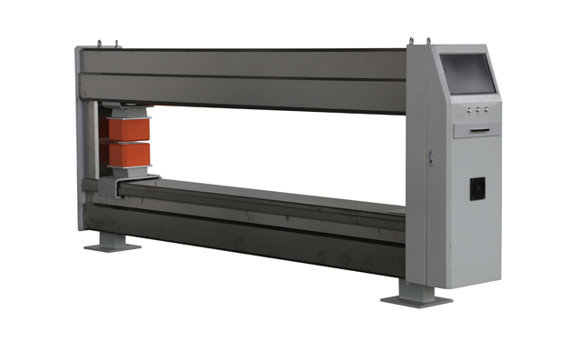
This thickness gauge adopts advanced nuclear physics detection technology, with signal acquisition and thickness control centrally managed by an industrial-grade computer. It features high measurement accuracy, long-term continuous operation capability, and low failure rate. Customization is available to suit various specifications and production needs.
Widely applied in cast and calendering production lines for materials such as CPP, PE, PS, PA, PET, PC, and PVC, the system provides reliable online thickness measurement and control solutions for film, sheet, and board products.
Applicable Materials:
CPP, PE, PS, PA, PET, PC, PVC films, sheets, and plates.
Technical Specifications
Measurement Principle
Radiometric Measurement Principle
The system adopts a radiometric method for thickness detection. Radiation emitted from the source penetrates the measured substrate. Part of the radiation is absorbed by the material, while the remaining part is received by the detector on the other side. By analyzing the intensity change of the transmitted radiation, the system calculates the surface density and thickness of the substrate.
As the radiation passes through the material, its intensity attenuates exponentially according to the following formula:
I = I₀ * e^(–μh)
Where:
· I is the radiation intensity after passing through the material
· I₀ is the original intensity
· μ is the attenuation (absorption) coefficient
· h is the thickness of the material
Different materials have different μ values. In general, the higher the material density, the greater its attenuation coefficient. For example, lead has one of the highest densities among non-radioactive natural elements and thus provides strong radiation shielding.
Laser Measurement Principle
The laser thickness gauge operates based on the principle of triangulation. An integrated triangulation sensor measures the distance between the mounting bracket and the surface of the object. By subtracting this distance from the known fixed distance between the upper and lower sensors, the system calculates the object’s thickness.
When the thickness of the measured object changes, the laser beam emitted from the laser transmitter reflects off the object’s surface. The reflected beam strikes a different position on the receiving sensor. Based on this positional shift, the system performs geometric calculations to determine the variation in thickness. The thickness result is output as either numerical data or in graphical form.
During measurement, two laser displacement sensors (positioned above and below the substrate) operate in opposition, simultaneously measuring the upper and lower surfaces of the material. The thickness is calculated as:
h = L – A – B,
where:
· L = distance between the two sensors,
· A = distance from the upper sensor to the top surface of the material,
· B = distance from the lower sensor to the bottom surface.
Characteristic Laser Spectrum Measurement Principle
This method is used for measuring the coating thickness on plastic substrates by utilizing characteristic laser spectrum technology. The laser beam generated by the spectrum emitter is partially absorbed by the substrate, while the rest penetrates and is received by the detector. The system analyzes the change in laser intensity and its correlation with substrate thickness to calculate the surface weight and thickness of the material.
The measurement is governed by the formula:
I = I₀ * e^(–gμh)
Where:
· I = received laser intensity after passing through the material,
· I₀ = initial laser intensity,
· μ = mass attenuation coefficient,
· g = material density,
· h = thickness of the measured material.
Infrared Measurement Principle
Certain adhesive coatings exhibit strong absorption characteristics at specific infrared wavelengths. When infrared light at these specific wavelengths is directed onto the coated material, certain components within the coating absorb a portion of the energy. The higher the concentration of the target component, the greater the absorption.
The system analyzes the change in infrared intensity and its correlation with the coating’s properties to calculate the surface weight and thickness of the measured layer.
Industry-Specific Software Features
· Intelligent operation with user-friendly interface
· Real-time display of measurement data
· Powerful visualization tools: real-time thickness graph, overlaid curve plots, zone-specific trend charts,
and 3D longitudinal/transverse trend views
· Professional data logging and management based on a database system
· Full traceability with large-capacity data storage (up to 3 years)
· Measurement parameter templates for different process recipes; quick access at any time
· Fixed-point measurement capability
· Auto start/stop of sensors and scanning function
Communication and Bus Interfaces
· Seamless communication with MES systems
· Support for data exchange between host PC and LAN via bus communication
· Compatible with PLC, Ethernet, RS485, RS232, and other bus protocols
Automatic Die Head APC System
· PLC-based control for automatic adjustment of thermal expansion bolts on the die head
· Control precision: ±0.2% FS, within the scanning test resolution
· Fiber-optic communication between die head control system and host system
· Heating bolt adjustment trend display available on the main screen and die head auxiliary screen
